Thursday, May 28, 2015

Part 7- Finishing up for the final installation

With a few of the bugs worked out, the system is running through its final paces, before its to be installed in the car. While this is testing, time to turn my attention to the other part of this, my bike.

This will be the first time I have equipped the bike with APRS. I ordered the Byonics TinyTrak3, and they arrived ready to put together. I was surprised, both were easy to put together, once all the resistors were sorted, and the parts inventoried.


I did make a small modification for the bike tracker. I changed out the big T3 LEDs for some smaller, less power consuming SMT leds, and changed the current limiting resistors from 1K up to 3.3K. This reduced the intensity, and the power pulled by the LEDs, and saved me a few milliamps when operating. Getting the system working was easy, Byonics provides a free configuration software package in both Windows and Linux, to configure these guys. Hooking them up requires a null modem between the encoder and the computer...not a problem, I just used female to female jumpers and crossed Pins 2 and 3 on the serial ports, and passed Pin 5 (gnd) straight through. They connected to the computer instantly, and I configured them in a couple of minutes.

Finally I hooked up the cable I bought from Byonics to the UV5R handheld radio I have, applied power and checked my FTM-350 for a broadcast packet....in 3 minutes, success!


The GPS wasnt attached, so there is no location info, but I still need to whip up a serial cable for the GPS, in all accounts, this part is done! I have a handlebar bag, that all of this will fit nicely into. Im still trying to decide whether to add a small whip antenna, or just see how the UV5R does on its own. If I have time, I might whip up a little antenna, but its not necessary. Supposedly where I am riding in a couple of weeks is covered by some wide coverage digipeaters, so we will see how it works.

Also with the configuration software available for Linux, if I run into a problem, Ill have my laptop with me with the software on it, I can hook up a quick null modem, and reconfigure if necessary.

Finally the burn in for the console is about done. I had a wiring mistake on one of the controllers. I made the software serial pins 6 and 7 not 7 and 8.....so instead of unsoldering the headers and moving them one pin up, I just reloaded the code, and changed the software serial ports to pins 6 and 7....done.

The new finish is dried. I used a textured finish that adds just a little texture to the overall console. I didnt want to use glossy black paint, the texture added a nice touch


Next is to obtain the power taps for the cars fuse box, and run the wires. Since its Thursday, Im gonna wait until the weekend, when Im not rushed. So thats all for now

Happy coding!


Tuesday, May 26, 2015

GPS project Part 6

So the project continues, and really its almost done. I ran into a major snag, and maybe by posting it Ill get a little feed back to fix the problem.

I ordered a TFT screen. Its nice and in earlier posts you see that I had it working. Its was working in a static state. Static state being that I could input the labels I wanted on the screen, and enter in dumby data to see where things lined up on the screen, how colors looked, and placement. What I didnt know was TFT really really sucks for displaying real time data, especially in SPI interface mode. What happens is the data is written to the screen, in order to then display a new piece of data the screen must be erased and rewritten. When using  say a 20x4 LCD this is not an issue you can simply print some blank data " lcd.print( "       "); and you are done. Then all is needed is the new data written back. It works and is pretty fast, especially on I2C bus. What I discovered with the TFT screen is the whole screen needs to be blanked out and then refreshed, or one trick is to write and fill a black rectangle where the old data was, then print the new data. While this is similar to the LCD screen printing blank spaces...its too slow, at least for now. At a later date Im gonna try using the 8 bit mode instead of SPI, but Im under a time constraint, itll have to wait.

SO, yet another change. What I did was use 2 LCD screens...so why two? If driving down the road and you just want to have time and temp displayed, then you can turn off the bigger GPS screen and vice versa...or any combination there of. SO I broke the original sketch up into two parts, rewrote a few line of code for the LCD screen I2C bus displays.....enter my next problem

When I ordered the 16x2 LCD it came with an I2C bus module already soldered on the back. What I found out after tracing down the problem was BOTH displays were using the same address 0x27...great. You can fix this pretty simply by demuxing the clock (SCL) line so that one display sees the SDA line HIGH, and will ignore the data on the bus, allowing the other display to change...and vice versa...again Im under a time constraint, no time for rewiring things and adding boards. I could have done it, I chose not to. I fixed the problem by just adding another MCU. I have several of these Pro-Mini328 MCUs, fully arduino compatible, and there are cheap, at just a few dollars each. I think I paid like $4.50 each. I cant make them that cheap...SO I always keep a few around. In this case, it saved me a lot of time.


This is obviously the 16x2 undergoing testing. You can see the Pro-Min328 on the beardboard. The gray cable is connected to the GPS, and I stripped off the code to display just the time and the cars interior temp. Hard to see but the LM35DZ is on the breadboard in the upper right corner.


This is the final design for the 20x4 LCD, nothing fancy. Im displaying the latitude, longitude, the number of satellites the GPD receiver is seeing, and the current Altitude in feet. The "GPS" in the upper right corner means the receiver is locked on, if the receiver is not locked on, then the "GPS" is simply absent from the display.

Around each display, as you can see in the upper picture I made a Plexiglas bevel to go around each display. Its just .20inch think Plexiglas you can get at any home supply store, then just measure and cut it out. Be prepared to do a lot of filing to make the LCD fit. I now dream of owning a 65W LASER so I can cut my own, in the meantime, I do a lot o filing.....

That's all for this addition. In the next part, we will finish the wiring, and mount all the stuff ready for the final install in the car!

Happy Coding!

Tuesday, May 19, 2015

Part 5.... the firmware

So having all these parts and assemblies together really means nothing if they dont do something cool, and the firmware is what glues that all together. As I mentioned I was under a bit of a time constraint, so it was easier to look and some examples and libraries to get what I needed, and understand whats being done. Normally I write all my code, but right now, I need stuff to work, Ill make mods later.

Credit where its due. I looked at several libraries, .cpp and header files, and examples from folks like Limor Fried ( LadyAda), Mikal Hart ( TinyGPS++) and others to see what I could find. Mikal Hart has written a great GPS library, and Ladyada some great code on the TFT screen, so why reinvent the wheel...

The firmware:

First we need to set up the libraries, and the initialize things


I need the library SPI to run the TFT screen since its SPI interfacing. The TinyGPS++ library is to interface with the GPS receiver, and gives us the tools to parse out what we need from the NEMA stream. The two ADAFruit libraries are to use the graphic capabilities of the TFT screen. Finally we set up the Software serial, address the pins to use, make our definitions. Last, initialize the analog pin A0 (CARTEMP) , so we can read the temperature from the probe in the car interior. Thats everything we need to make this work.


Next we setup things:

There really isnt any magic going on here. All we are doing is setting up the serial ports. The software serial port connected to the GPS, will send its data to the arduinos serial port. You can then debug the data, which is helpful. The rest of the code here is nothing more than setting up the screen in landscape more  ( tft.screenRotation(1)) clearing the screen, outputting a message to the user thats the system is booting up, waiting a second, and telling them its done. In the final version, the delay put in here ( delay (1000)) will be changed to delay(30000) or 30 seconds to allow the GPS time to do a cold boot and acquire the satellites. I may or may not drop this in the future, and just tell the user its is powering up, but thats later, again time is not on my side. This needs to get done, playing with user interfacing is a later project...

The VOID loop:

This is where everything get done. 


ok.. the fun part. In the first part of this the code is telling the arduino to look at Software serial port (ss). Its going to see if there is data there. If there is data available, then decode the data and jump to the void loop " displayScreen".

If there is no data available after 5 seconds, then it jumps to the routine that throws the warning on the screen stating that the GPS is unlocked, and stays there until there is data available

In the loop for the display screen, I have shown the part ( and all the other parts are the same) for parsing out the data ( in this case latitude) and displaying it on the screen. This is repeated in one form or another for longitude, altitude, speed and the number of satellites the receiver sees. All the " if " loops are, is if the code sees a change, for instance " if (gps,location.isUpdated())" then parse out the new value and display it...its rather simple. Mikal Hart does some great explaining on what the library does, and how to use it, its worth looking at the examples and understanding what its does.

Ima bonehead:

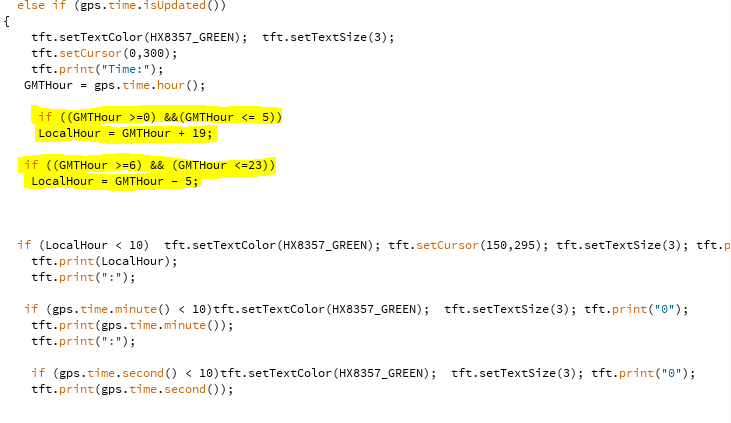
As I have mentioned Im under a time constraint. Cute things and added features will come later I just need functionality. When I wanted to display the clock on the screen, I parsed out the time from the NEMA data, and used some examples to update the hour, minutes, and seconds. There were two small problems though. One of the people using this doesnt know what UTC time is ( the standard time sent in the NEMA stream from the GPS satellites.....and we are under Daylights saving Time. If the satellites are sending UTC time, how to account for all of this.....enter my boneheaded bandaided work around.....dont comment on this part of the code...it works, for now until next November when the time changes locally....


This is the dumbest code I have ever written, and the first thing Ill fix later. Basically this code accounts for GMT time, converts the GMT time to DST for the central time zone in the USA, and then make corrections if the time falls after 00:00 local time. In reality it works, its bad code, but I didnt want to sit there and add the code to figure out what day it was, and the month, and then add in to fall back an hour in November, and spring ahead an hour in March.....yes it can be done, this is a bandaid to make it work ...FOR NOW...I get a chuckle everytime I see this part of the code....

Finally the code for the car temperature code. I just wanted to add this, as a cute feature. Its taking an LM35DZ Celsius temperature probe, and converting the temperature to Fahrenheit, and displaying it on the screen. I may move this down to the APRS radios heat sink and monitor the temperature there...its probably the only real " bell or whistle" I added

This about it....nothing fancy. Ill add the entire code in the future for anyone that might want it to adopt for their needs.


Happy coding!

Shell done, now wiring..Part 4

So the project progresses. With the code written, all thats left is the bugs and the wiring, and Im sure there will be bugs, but maybe not. Once the full system is bench tested, basically there is nothing left but the wiring, and making it pretty.

I went ahead and did the final fitting in the car. I have to admit I was able to make a pretty nice fit, which is what I wanted. Though its not original to the car, I didnt want it to look sloppy after all. While Im testing the code, and burning the system, I put the first of a few coats of paint on and started the wiring.


Basically the ugly part of any project, wiring it all together. This is a picture of the start of that process. You can see the APRS radio is now dry fitted in its new home. The wiring here is for the panel switches, the two 5V power supplies, and the mobile phone chargers. My calculations Ill need 2 circuits from the car, a 7A and a 15A. The 7A circuit will power the 5V supplies, and the chargers. The chargers pull 2A each, the power supplies are 2A each for a total of 4A, plus a little head room so no fuses are blown. The radio is a 55W radio and pulls 11A on high power. Ill probably run is on medium power which pulls 7.5A@25W. This still needs the TFT screen hole cut, and the arduino wiring install but that will be soon enough, that mess is still under test.

The GPS receive and the power supply I designed are now finished and work great. I found some commercial enclosures that look nice. It was a bit of a fit, and I almost got it too close, but I ended up using a perfboard, and some headers, putting the receiver next to the power supply, they snugged into the box just fine. The antenna is not shown here, but will be attached to the reliever and mounted in the enclosure as well. Its been tested and it all works. Future revisions the perf board will be a PCB....and the jumpers will be gone as well....


The purple board is the supply. I designed to interface with the receiver, and had Osh Park fabricate for me. They are awesome on turn around time. From design. to submitting , to boards in my hands, 9 days.....coolness. You can check them out at www.oshpark.com.

More later...Happy Coding!

Friday, May 15, 2015

Springtime Project Part 3 - GPS and the arduino Parts and more parts

So the console is coming along nicely. Lots of sanding, and checking to make sure the part I had to build up manually still make for a good fit in the car.While I have been doing that each night after work, I got to the point that I needed to paint, but I have decided to hold off on that, until I get everything in from all the parts houses.

SO, I thought it best I sit down and write some code. Im in a bit of a hurry, so I figured I would see whats out there that people have done, and perhaps get some ideas from then as to which way to go.

First off I got the GPS receiver and antenna in from New York. I came to me in 3 days, a new record for the Postal Service, who still frustrate me on a daily basis ( Im still waiting on parts that should have been here days ago). Its straightforward....The receiver receives the GPS data and output the NEMA data on a serial port...easy. You have to watch though the receiver runs on 3.3V....NOT 5V!

I found the libraries on the internet. The TinyGPS+++ written by Mikal Hart had everything I needed and some good examples to build from.


Using software serial I was able to get NEMA data into the arduino and out put the data to the serial port from the arduino. So within little time, I already had the foundation to get this going. Serial ports are cool in that you can literally split off the ports, or data lines and feed multiple inputs with one output. Im my case Ill have to feed the arduino, and the radio encoder. Again its ok to feed multiple INPUTS with one OUTPUT, not the other way around. I guess I should mention that the inputs your feeding really need to be of decent impedance. Really low impedance devices, can, in some case load down the signal being transmitted over serial and the other device may not decode it correctly. I did some calculations and Ill be ok feeding the arduino and the encoder!.

Next I wanted to add a TFT screen so I could see and make sure the GPS was locked on and outputting data. I also added some cool things for fun, but more on that later. I chose the 3.5 inch TFT breakout from Adafruit. With the SPI interface, though its not lightening fast, I was only displaying a few things on the screen so I was ok on speed.....

This is the TFT screen. I wont be using the touchscreen part right now, but in the future. I wired it up using SPI interfacing, and it worked right out of the box after soldering the header and jumper, and wiring it to the arduino.


This is the initial testing of the TFT display. I was playing around with the placement of things on the screen. The final version is about done and can upload it. I have it so that if the GPS receiver becomes unlocked, then you'll see in the upper right hand corner, the warning and of course its red. Ill have more to show what happens when its working. I'm still waiting on the 3.3V power supply parts from California!!! I hate the postal service!......Note...you cant run this TFT screen on 5V and hook up the GPS receiver to the 3.3V supply of the arduino and expect to run both, there isnt enough current to run the arduino and have it supply the TFT screen and the GPS.....so I wait.

Ill have more on the sketch that run all of this, in the next part...

Happy Coding!

Building the shell

So I had the idea for the new console. After taking all the necessary measurements and making some rough cardboard templates, I set out on the design. I finally had to just make a decision, because Im the type of person that will changes things amid stream ( I have already the designs in my head for version 2 of this project)!

The body of the console is simple. I used some 3/8 inch plywood. The reason is that its lightweight, easy to shape and work with. With the cardboard templates I made, all I had to do was transfer the templates to the plywood, mark it off and cut it out.


This is the rough version 1 of the new console. Took no time at all to cut the body out, the templates made it really easy. Next with a little work on sanding with the demel tool, I got it to fit just right. I did discover that it needed some bracing, so I add some braces for the front.


Just some 1x2 inch strips to the back of the front piece allowed me to attach the front and give it some added support. Ill learn later, that I should have gone a step further, but that would spoil all the fun.

Lastly, I got to thinking of a finish. I had all the placement for the parts I wanted to mount on the front, but I didnt know if I wanted to cover the console in either a vinyl, to match the interior of the car, paint it to match, or perhaps use a plastic paint. After reading the reviews on the plastic paint, that was ruled out. Covering in vinyl would make it look cleaner, but I didn't want any seams, and I'm not that great with that medium. So I came up with this....


I figured to help strengthen the console, I could add car bonding compound. In reality this was the best choice and the biggest headache. While the bonding compound nicely hid the wood grain, it also was a bear to apply, and sand. I was forever sanding and filling small holes that I had left. In the end, Im going to go about this differently in the next version, but Im under a bit of a time constraint here, so it'll have to do for now. Still looks good, just time consuming......

So what was the lesson I learned in supporting this console and making it stronger? After only bracing the top piece, sanding, and more sanding.....it was time for primer. So I cut the holes for the added parts, and took it to the garage to paint. I applied 4 coats of primer, sanding between coats....it was looking great...then the dog....

I have a hyper....very energetic rat terrier that likes to jump. The console was in the garage and apparently he got overly worked up....long story short...he jumped, hit the stand my console was on, the stand and the console crashed to the cement floor, cracking the top and a few other bruises....SO back to the car bonding compound, more sanding, and more primer. This time though I had to build up on of the corners that was smashed when it hit the floor, matching it to the other side, Im now a week behind where I originally was.

In the mean time, the console switches arrived, the fabricator sent me the power supply boards I designed, and the parts are here for the supplies. Time to heat up the soldering iron, and track down the TFT screen I'll use.

Happy coding!

Thursday, May 14, 2015

Springtime car/radio project

So with the repeater project stalled while trying to find more hardware ( duplexers and good radios are in short supply right now, and I still need a location as well) I decided that I would switch and do something on a smaller scale that was fun.

I had purchased a Honda Element a year or so ago, and had installed my 2M radio in it. With little options I just Velcroed it to the dashboard. It was ok, but I didnt like the mic hanging down, and it sitting in the sun all the time, so I eventually removed it and started to think. There was alot of room between the center console and the actual front of the dash....got me to thinking, what if I installed it down there, out of the sun ( and sight) and uncluttered the dash....so the planning began.

What actually just started out as a radio install, actually ballooned in to a much bigger project. I have biking season starting in a few weeks, and I have my usual BIG bike tour across the state of Kansas ( about 550 miles, over 9 days). This year my girlfriend is going to go with my son and I. She will be driving my car, and supporting us. With her separated from us most of the day, wouldn't it be cool if she could know where I am on my bike ride, and better I know where she is as well....enter APRS.

APRS in the amateur radio world is Automatic Position Reporting System. Using the amateur frequency of 144.390Mhz, licensed hams can report their positions in pretty much real time. If you want to look, hit the web at www.aprs.fi. There youll find exactly what I am talking about. SO, the project ( like so many I do) blossomed into something more.

I decided that I am going to outfit not only the car, but my bike with APRS. Its really isnt that hard to do. APRS encoders have made leaps and bound using either PICs or arduino. There are many commercially available encoders ( that send data from a GPS to the radio) on the market. There are even radios that have these features built in. My first decision was to use an older radio and encode the data for broadcasting my position. This way I could use another radio to talk to folks and use the dedicated radio to report my position....I had the gear, so the planning began.

Below is the version I settled on. I also added a TFT 3.5inch screen so I can monitor the data being transmitted by the radio. As youll see, I also parsed out more information from the GPS data stream so I can read speed Im traveling, altitude of the car, and the current time.

The GPS provides once its locked on, data to the arduino and to the Byonics encoder. I have to mention I used the encoder because its simple, came in a kit form I could build, and was reasonably priced. I have no stake in Byonics LLC, its owned by a fellow ham in Arizona. Their web site is www.byonics.com if you wanna check them out. I also wanted to use my own GPS, and not some pre packaged GPS. I wanted it interface-able with the arduino on the lowest level. I wanted to control what I parsed, and how I parsed the information...hence the reason I just didnt buy an encoder/GPS all-in-one and plug and play...after all I wanted a system I designed, and built....I need parts not total assemblies.

In the next part youll see what I got and how its put together..........

Happy coding!